Reactive power compensation: three steps to financial savings

Non-linear loads such as UPSs, computer PSUs, LED lamps, inverters, air conditioners, etc. draw mains current which is distorted and off-phase with voltage. One of the negative effects of the operation is the generation of capacitive reactive power into the grid.
This operation is charged extra by DSOs (applying liquidated/contractual damages), and the costs can be considerable. The issue can be solved in several ways, although one of the simplest and most effective solutions is a dynamic var compensator (DVR). A dynamic var compensator monitors the grid and provides real-time corrections to power parameters in order to maintain the preset cos(φ).
What are the three steps to specify and select the right DVR? This post provides a real-life case of an electronic equipment manufacturer.
Step 1: Profitability analysis of a reactive power compensation application
When the power bill comes and reads extra charge for reactive power consumption or generation, what needs to be done is a profitability analysis for a potential reactive power compensation. In this case, the extra charge on the power bills amounted to approximately 6000 PLN net (1400 EUR). The manufacturer decided to have a DVR installed.
Step 2: Measurements and power bill-driven calculations
Step two is about measurements and running calculations based on the power bills (invoices) to help with the selection of a properly specified DVR. This was done by choosing to measure the power for one week, by which a power load profile of the entire facility was generated. Sonel PQM-711 was used, a Class-A power quality monitor with a set of F-3A flexible test clamps. The measurement data was analysed in the Sonel Analysis software package. The measurements had a 10-second averaging period to capture a precise power load profile.
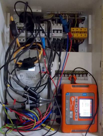
Figure 1. Sonel PQM-711 power quality monitor shown deployed and measuring
The reactive power levels varied across power phases, which was why the DVR power rating had to match the highest reactive power of all three phases. The highest power level, Q=3.5 kVar was found on line L1 (Fig. 2). This was enough to specify a 10 kVar DVR (with 3.33 kVar/line). The manufacturer’s facility had CAPEX projects with more power loads planned and it was decided that a 15 kVar DVR (5 kVar/line) would be better to have a capacity reserve for the future.
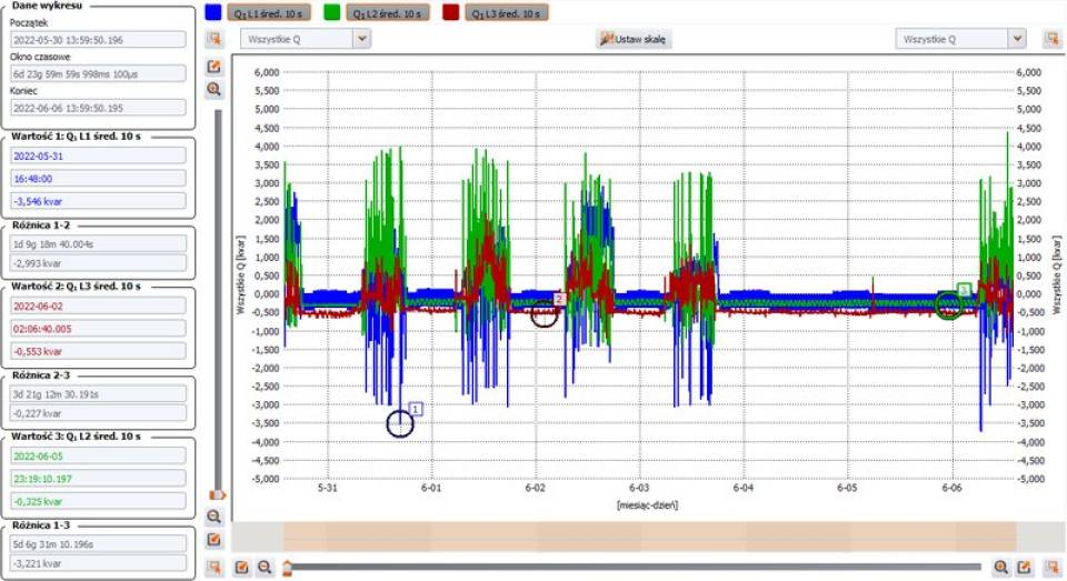
Fig. 2. Weekly reactive power trends per phase, before DVR
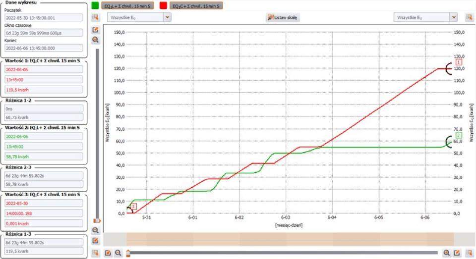
Fig. 3. Weekly graph of three-phase reactive power, before DVR
(Green - inductive power; red - capacitative power)
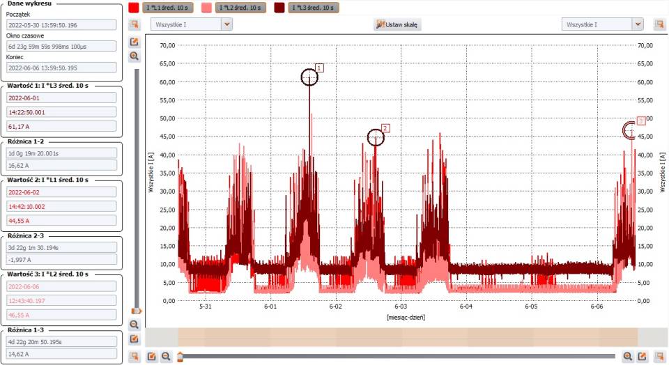
Fig. 4. Weekly current trends per phase, before DVR
Step 3: Buying and installing the DVR
This step is when one buys and installs the specified DVR, followed by verifying its proper operation. The facility in this case received an LKD 15 DVR by Lopi, which features excellent performance parameters with high compensation efficiency. The LKD DVR series are the world’s only based on SiC (silicon carbide) capacitors which provide a loss level of 12.5 W/A. Based on the currents measured on site (Fig. 4), Class 0.5 60/5A current transformers were selected to ensure the highest quality of reactive power compensation. The CTs were specified according to the average current levels measured with 10 s averaging and the planned cable core size.
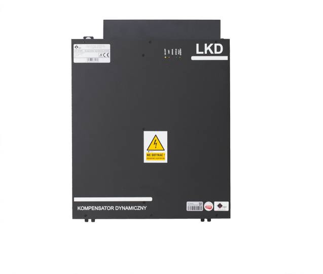
Fig. 5 LKD15 DVR faceplate
The DVR was wired in parallel at the main power switchgear. For a correct setup of the DVR, its manual specifies it needs to be connected to Wi-Fi, the installer account needs to be logged into, and the CT parameters need to be configured (the primary current level and CT class). The remaining standard factory settings ensure correct reactive power compensation.

Fig. 6. DVR-to-grid wiring diagram
To verify the CTs are wired correctly to the grid, the Current Transformers table needs to be displayed in the Status Reading tab (Fig. 7). The table shows the CT connection lines and their live status. Any wiring mismatch of the CTs is shown in the same table which is a great help in re-wiring the DVR.
Fig. 7. Table showing correct CT wiring connections
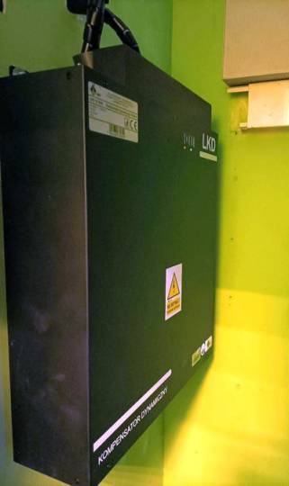
Fig. 8. LKD15 DVR shown installed on site
Once the basic configuration setup and wiring verification were completed, the DVR was brought online, after which it began to work effectively.
For a comparison, a week-long run of the same measurements was repeated. Fig. 9 shows the capacitative reactive power level trend, which was zero in the whole interval. This was a proof the reactive power compensation worked, with the cherry on top being the power utility bills, with the extra charges for reactive power slashed to zero.
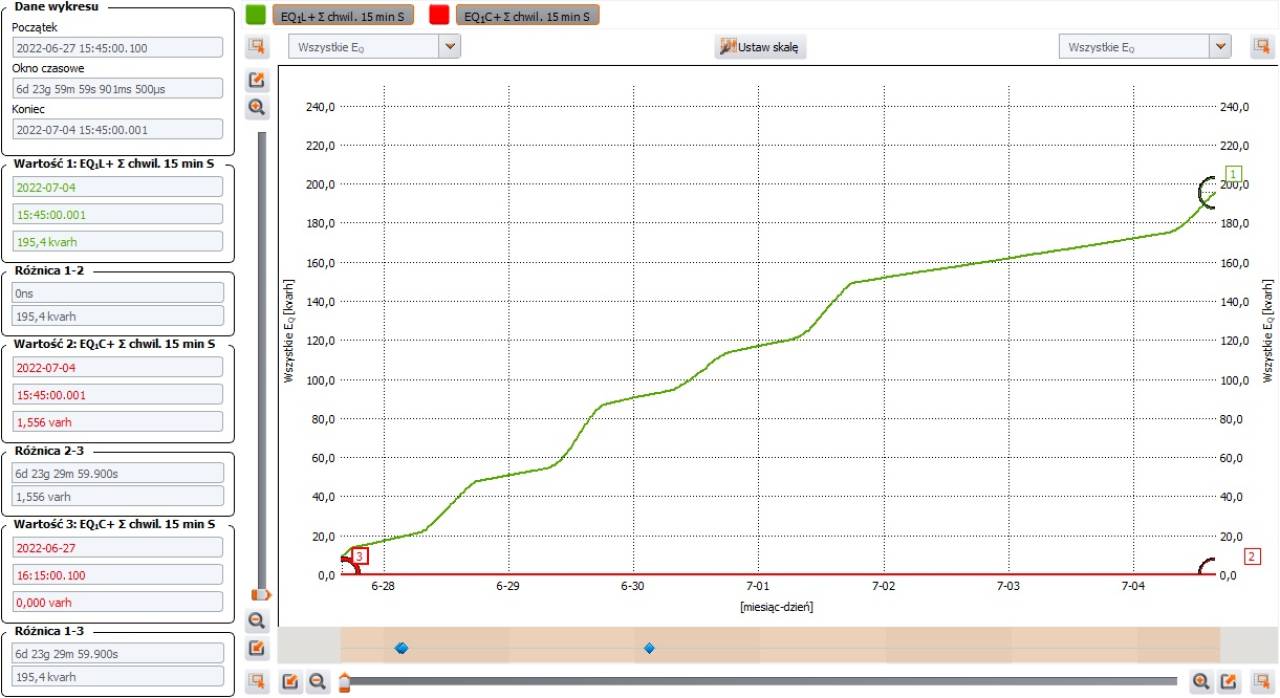
Fig. 9. Weekly graph of three-phase reactive power, DVR online
(Green - inductive power; red - capacitative power)
DVR with a PQM mean tangible savings
For the case studied here, the expense on diagnosing the issue with a Sonel PQM-711 and installing the Lopi LKD15 DVR will see a return in 18 months after commissioning the DVR, followed by tangible savings of several thousand PLN a year. In the modern world dominated by power electronic applications, DVRs provide a reactive power compensation solution that is very effective and simple to specify and install. The LKD DVR series can compensate inductive and capacitative reactive power in each phase line in separation. Reactive power compensation aside, the DVRs can filter out higher harmonics and balance out active power. The Sonel PQM series, on the other hand, provide reliable measurements and intelligence for choosing a DVR.
MSc Eng. Marcin Szkudniewski, Sonel S.A.
MSc Eng. Piotr Matera, Lopi Sp. z o.o.